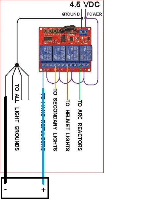
1/6 DIY - Remote Controlled Hulk Buster Lighting Tutorial / Project

Collector Freaks Forum

Help Support Collector Freaks Forum:

This site may earn a commission from merchant affiliate links, including eBay, Amazon, and others.
4 of the 8 battery circuits done, I'll work on the helmet and chest reactor tomorrow


I worked the back battery compartment today and had some success and some disappointment

First the disappointment, I could not find any batteries with enough power to operate the relay board.

It uses 220 mA which is almost a ¼ amp and that is a lot of current for batteries so this will only run with a power supply.


Now for the success.

I was able to modify the battery compartment enough to mount a power supply jack in the compartment and it is hidden with the magnetic panel.


I had to use a hot Exacto knife to open up the left side of the compartment. I did this because I didn't know where any of the factory wiring was and the hot knife method is a lot less aggressive then drilling holes


I was able to pull 2 sets of wires though the back. One set was to run power to the battery compartment tabs which in turn powers the torso lights and the other set was for the power supply jack so I could run power to the jack to the board


Once all the wires were soldered I used hot glue to secure the jack, it’s not pretty but it works well because it is a fixing agent and an insulator so not only do it secure the jack it also protects the exposed wires

 
Wow looks like you did a good job looks very clean . Did you consider putting the jack in one of the feet ?

If you did that you could route / cut a hole in your display base and then the cable could connect under the feet and would be hidden . But would require routing a cable thought he leg and knee , so not sure if its possible.


I use the battery compartments because the jacks are pretty big and you always have a panel to hide everything except the hole for the plug.


I don't think the foot would be a good idea because this weighs 18.7 pounds and that could easily damage the plug.
 
Final test before I glue the wires to the back of the board and cram it into the torso.


I formed all of the wires to fit closely to the back of the board and then I used a test piece of the 3D printed flooring to provide protection for everything.

I hot glued it to the board and then I carefully maneuvered the board into the torso. There is a piece of foam under it so it sits right.

I am sure that the original half Mark 43 figure will fit and I could include it on the Relay Board but for now my Hulkbuster will be in Maintenance Mode" as it sits in his wine cellar bay


Here is a video of the final test. Now I need to set up bay for remote controlled power because I don't want the relay board on all the time


Stupid question. New question, are all iron man figures ran on 4.5vdc? as long as I am wiring to the battery compartments and not directly to the led, there is no need for a resistor, regardless of what voltage the battery I am replacing is?
 
Last edited:
Sorry if I missed the answer somewhere in this thread, but how are you getting power from the relay board to the battery compartments? Did you solder wire directly to the contacts in the compartments?

Thanks!
 
Stupid question. New question, are all iron man figures ran on 4.5vdc? as long as I am wiring to the battery compartments and not directly to the led, there is no need for a resistor, regardless of what voltage the battery I am replacing is?


As long as the compartment holds three 1.5v batteries it will be 4.5 volts


Sorry if I missed the answer somewhere in this thread, but how are you getting power from the relay board to the battery compartments? Did you solder wire directly to the contacts in the compartments?

Thanks!


Yes, I soldered wires to the to the battery contacts and ran them to the relay panel.


The video demonstrates this in a couple places
 
Hi there, great work on the lighting of this figure! I too am doing this myself and just wanted to ask about the wiring. So you have the jumper wires going into the middle terminal of each channel, and from terminal marked CK you have the power going to the LEDs in the figures, but where are the wires coming from the neutral terminal (or ground) going to. I can see it goes into the terminal next to the power one from the power supply, so does the other 4 ground wires going into the same battery compartments but just acting as the neutral wire?

So what I mean is you have a positive wire going into the positive side of the battery compartment, and then from the negative side you have a black wire going all the way back to the ground terminal next to the power terminal on the board?

Thanks! :)

EDIT: Here is an image I made based off yours. Is this how you have your wiring set up? The box being the battery compartment.
CilykDt.jpg
 
First let me say that it is fantastic that you are doing this yourself, if you need more in depth tech support pm me your number and I'll call you if my schedule permits.


I don't exactly know what the blue line is in your revised drawing but if I am understanding what you are asking then YES

Each battery compartment has 2 wires running from it to the relay board.

At the relay board the + battery compartment wire goes to any of the relay 4.5vdc outputs and the - battery compartment wire is just spliced together with the ground from the 4.5vdc Power supply.


The contact block with 2 screws (top right of the picture) is Power In for the relay panel.

DC circuits are simple, all of the grounds can be connected at one point and all you have to do it interrupt the positive lead (via the relay) to control the lights
 
Thanks for the input! The blue line was just meant to be one of your cables drawn to the positive side of the compartment lol. I plan on lighting up all my Iron Man/War Machine figures but I'm discovering different ways to do so at the moment. I also had an idea of buying a 4.5 adapter and plugging it into a female barrel jack which has a positive and negative terminal at the end of it and connecting my dummy batteries to it. It pretty much eliminates the use of a channel board but I feel like I need something else, sounds too simple doing that.
 
Back
Top