1/6 DIY - Remote Controlled Hulk Buster Lighting Tutorial / Project

Collector Freaks Forum

Help Support Collector Freaks Forum:

This site may earn a commission from merchant affiliate links, including eBay, Amazon, and others.

Boba Debt

Super Freak
Joined
Jan 5, 2014
Messages
1,648
Reaction score
47
Project Over View


Soap Reactors are nice but I have been looking for a better less expensive way to remotely control the lights for my Iron Men Figures.

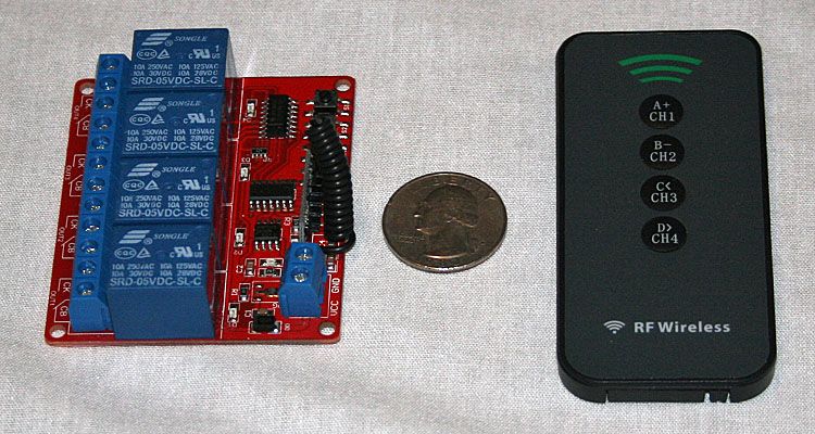
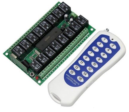
After a little research I found single and multi-channel RF relay boards on eBay for around $5 shipped for a single channel board up to up to $40 shipped for 16 channel boards.

For this project / tutorial I will use a 5vdc 4 channel board & the Hulk Buster Figure.


I plan to use each channel of the relay board to control different light circuits -


  • Ch 1 - Arc Reactors
  • Ch 2 - Eyes
  • Ch 3 - Secondary Lights
  • Ch 4 - Hand Repulses


I choose this board for 2 reasons

1. It operates on 4.5vdc which is the same requirement as the figure lighting so I can use a single power supply to power the board and the relays.

You could use a 12vdc board and power the board with a 12vdc power supply and then power the relays with a 4.5vdc power supply, but I don't know why you would do that


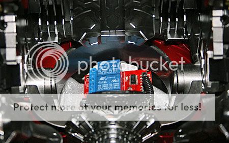
2. It's small enough to fit in the figure and it has enough relays to independently control the 4 different circuits I want to power.


Some things to consider

1. You can hook more then one light circuit to each relay. The max current capacity of the relays is 10 amps. That means you can run up to 10 amps through the relay which is A LOT

You could, in theory, control most of your collection with a single channel board but that would be boring.

Here are some variations

Use a 3 channel board to power the Arc Reactor, Eyes and Hand repulsors on 1/multiple Figures.

Use a 16 channel board to power 16 figures independently


Re: DIY - Remote Controlled Action Figure Lighting Tutorial / Project

Tutorial

I'll use the first 3 posts of this thread to consolidate all of the information and pertinent questions / answers

The first post will be an over view

The second will be the tutorial

The third will be an FAQ


I'm going to be working on the first 3 posts tonight, adding information, pictures and videos so check back to see what's changed


Introduction to Remote Controlled Relay Boards


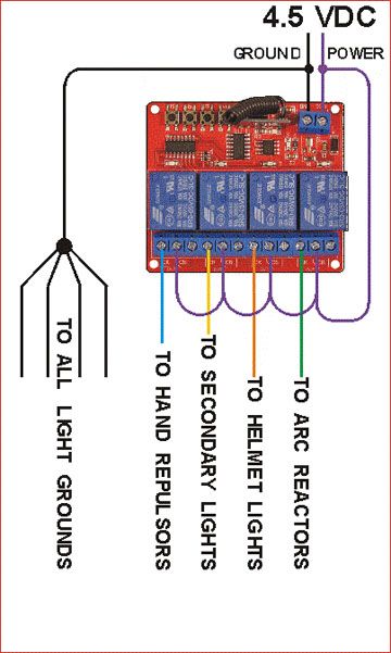
Basic Wiring Schematic

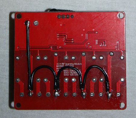
I used purple to indicate 4.5VDC power and black for ground. On my real board I will solder jumper wires to the back to keep the clutter to a minimum


Back of Relay Board with Power Jumper Wires Installed.

I'll attach the battery box to the back of the board to protect the exposed wires & solder tabs


Arm Modification & Wire Routing Basics
This is very complicate to explain but this video should give you a basic idea of how to modify the arms for wire routing


Relay Test Video Post 21

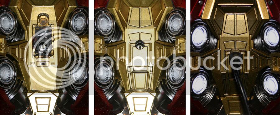
Back Battery Compartment Modification Post 22


[/URL]https://s131.photobucket.com/user/B...ops/Hot Toys/HB Mods 001_zpsekqrr2ij.jpg.htmlhttps://s131.photobucket.com/user/B...ops/Hot Toys/HB Mods 001_zpsekqrr2ij.jpg.html


https://s131.photobucket.com/user/B...ops/Hot Toys/HB Mods 001_zpsekqrr2ij.jpg.html

https://s131.photobucket.com/user/B...ops/Hot Toys/HB Mods 001_zpsekqrr2ij.jpg.html
 
Re: DIY - Remote Controlled Action Figure Lighting Tutorial / Project

Sonoff RF Bridge Review


Re: DIY - Remote Controlled Action Figure Lighting Tutorial / Project

This looks ****ing sick. Cannot wait to see what you do and hopefully I'll be able to use the LEDs on some of my Sentinel figures with this project, finally :wink1:
 
Re: DIY - Remote Controlled Action Figure Lighting Tutorial / Project

This looks ****ing sick. Cannot wait to see what you do and hopefully I'll be able to use the LEDs on some of my Sentinel figures with this project, finally :wink1:


This will not cover the installation of new LED circuits. It will just cover powering existing figure light circuits with a remote controlled relay board.
 
I haven't forgotten about this, I have just been busy with a blaster project on another forum
 
Have subbed, this looks very interesting. On a side note, what can I use to remote control my k-2so lights?
 
I don't have a k-2so so I can not provide any info on that for you, but if it has battery compartments like an IM figure the process would be similar.


I had to take a break from packing parts and I decided to wire up an arm and forearm armor.

It was more tedious then I expected and I don't think I could have done it without the decades of experience I have running wire harnesses in military aircraft and components.

The final result is internally run wires that do not seem to interfere with the articulation.

It would be impossible to explain everything I had to do to accomplish this but I will create a video overview to provide some direction for those of you that want to attempt this.
 
When you done with all the posts I will try this my self.

Question

Is this board safe does it have any circuits in place in insure that only 4.5 vdc is supplied and kept constant ?

Could you link me to the exact one you got ?
 
When you done with all the posts I will try this my self.

Question

Is this board safe does it have any circuits in place in insure that only 4.5 vdc is supplied and kept constant ?

Could you link me to the exact one you got ?


The board does not provide the 4.5vdc to the relays. The power supply for the relays provides the 4.5vdc for the lighting circuits. I explained this in detail in the video and the schematic and the basic wiring diagram in the 2nd post shows how you can use a single power supply for the boards operation and the relays output


I added a link for the board I bought to the first post.
 
I don't have a k-2so so I can not provide any info on that for you, but if it has battery compartments like an IM figure the process would be similar.


I had to take a break from packing parts and I decided to wire up an arm and forearm armor.

It was more tedious then I expected and I don't think I could have done it without the decades of experience I have running wire harnesses in military aircraft and components.

The final result is internally run wires that do not seem to interfere with the articulation.

It would be impossible to explain everything I had to do to accomplish this but I will create a video overview to provide some direction for those of you that want to attempt this.

So you're saying my two week soldering workshop from middle school might not pre qualify me for this project? :rotfl
 
So you're saying my two week soldering workshop from middle school might not pre qualify me for this project? :rotfl


Hopefully my info will help give people the direction they need to go to get it done.

My experience helped me figure out when to push wires or when to use a fish wire to pull them, direction and location for drilling the access holes, etc.

I am pretty sure the hand repulsors are the most difficult to run so the rest should be easier.
 
Thanks for your reply and explanation.

I have an idea you might want to use, for the arms you can see the wires a bit running in a few places in the uper arms , I though it might be cool to put them in sheet that would cover then and blend in to the figures colors and add some details.

Found some thing that matches the look of the plastic cable on the arms that you mentioned in the video . Its the sheath to a cable . You can see it pointed out by the green arrow.

This is the link to where you can get the cable from .

Q10024W016.jpg
 
Thanks for your reply and explanation.

I have an idea you might want to use, for the arms you can see the wires a bit running in a few places in the uper arms , I though it might be cool to put them in sheet that would cover then and blend in to the figures colors and add some details.

Found some thing that matches the look of the plastic cable on the arms that you mentioned in the video . Its the sheath to a cable . You can see it pointed out by the green arrow.

This is the link to where you can get the cable from .

View attachment 385139

That's some hefty gauge wire though and could be big and stiff to maneuver through the figure. You could use some foil and/or copper tape to run with small gauge for the same effect wrapping it. That tape is popular for railroad kits for conductivity. This would not be the ideal application example for what I linked below obviously but it allows to use very small gauge wires to run the + and - wires to the relay. You get the general idea, wrap up the cables with the tape.

https://www.amazon.com/Bullet-Face-Double-sided-Conductive-Electrical/dp/B01MR5DSCM/ref=sr_1_6?s=arts-crafts&ie=UTF8&qid=1514932241&sr=1-6&keywords=metal+tape
 
Thank you for sharing this. Much appreciated!


Sent from my iPhone using Tapatalk
 
Thanks for your reply and explanation.

I have an idea you might want to use, for the arms you can see the wires a bit running in a few places in the uper arms , I though it might be cool to put them in sheet that would cover then and blend in to the figures colors and add some details.

The back elbow armor is not in place for the video and the shoulder armor is pulled out as far as it can go.

Once I put everything back you can barely see the wires.

After they are painted black they will probably blend in.
 
I just had a very aggravating 3 hour ordeal.

I was modding the other forearm armor and had an intermittent continuity issue.

I figured it was what I had done but it ended up being the switch


So I had to remove guts of the battery compartment to give me enough room to just solder my wires direct to the LED leads. If you do this you have to make sure you include the resistor that is attached to the switch on the positive lead.

I'm guessing this drops the voltage for the LEDs (probably 3vdc), so I have to wonder why they just didn't use 4.5vdc LEDs or 2 batteries which is 3vdc
 
Back
Top